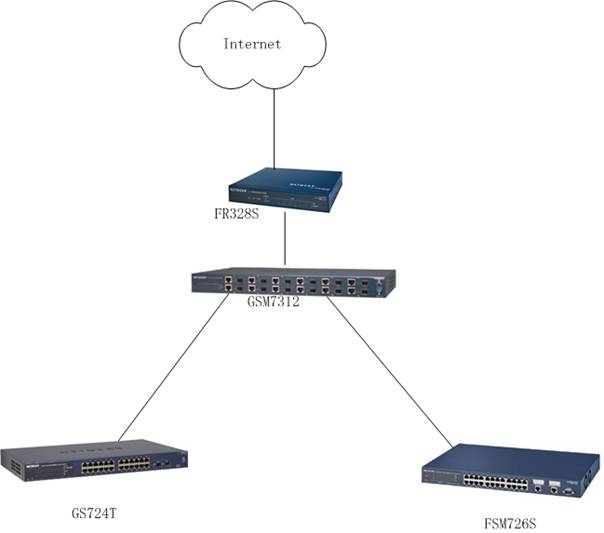
设置Netgear 7000系列交换机
(GSM7212,GSM7224,GSM7248,FSM7326P,FSM7328S,FSM7352S,FSM7352PS,GSM7312,GSM7324)的VLAN
请注意:FSM7328S,FSM7352S,FSM7352PS在设置里面的端口表示方法与其他7000系列交换机不同,其中物理端口其他7000系列交换机是Interface 0/2,在FSM73xxS可堆叠交换机里应为Interface 1/0/2。
一、通过Web页面设置 NETGEARGSM7312交换机Port-Base Vlan
设置目标:
增加2个Vlan:Vlan6(端口1);Vlan7(端口12),这2个Vlan间的用户不能互相访问,但可以通过共同端口11口访问路由器,其余端口保留在Vlan1。
配置步骤
- 使用9针串口设置线连接GSM7312交换机,进入CLI配置界面,使用(GSM7312)# Clear Config命令恢复出厂设置。
- 然后使用命令(GSM7312)#Reload ; 系统提示是否保存现有配置(选择YES)。然后系统重新启动。
- 配置GSM7312交换机管理IP地址为192.168.0.238/24,配置完毕后保存。
- 连接配置计算机的网线到GSM7312的端口10;
- 打开IE浏览器,在URL处输入http://192.168.0.238/,进入交换机配置管理界面。
- 点选菜单Switch>VLAN>config ;在VLAN Configuration界面的Default VLAN处选择进行端口配置,保留所有端口在VLAN1不动;
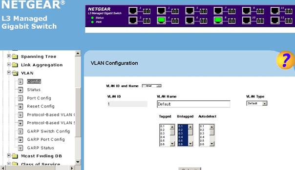
- 在VLAN Configuration界面的VLAN ID and Name处,下拉选择Create选项进行新的VLAN的创建。
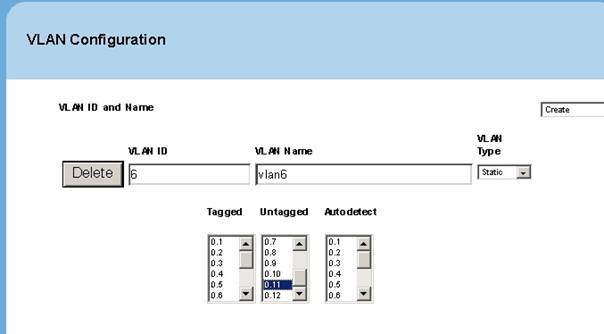
8.在VLAN ID栏里输入6; VLAN Name处输入:VLAN6 ;
VLAN type选:Static(缺省)
然后,按住键盘CTRL的同时,用鼠标点在unTag栏目下点选端口1、11,然后点“Submit”按纽保存设置。(见下图)
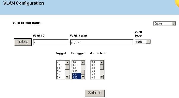
9.重复7-8步骤过程,建立VLAN7,添加端口11,12
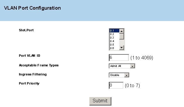
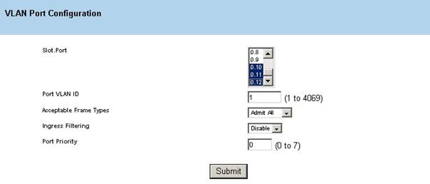
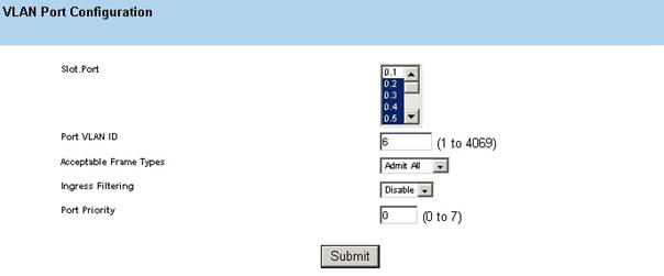
10.点选菜单Switch>VLAN>Port config ;在Port Vlan ID右边栏里输入:6;点选端口1;然后按”Submit”更改端口1的PVID;
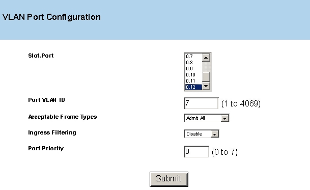
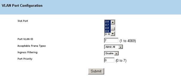
11.重复第10步,在Port Vlan ID右边栏里输入:7;点选端口12;然后按”Submit”更改端口12的PVID;
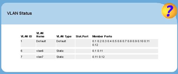
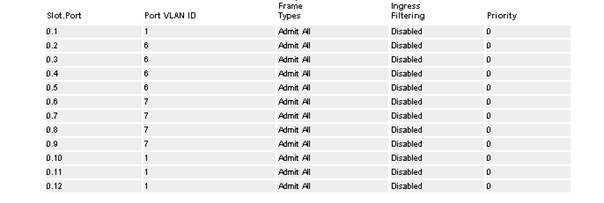
12.选择菜单薄Switch>VLAN>status ,查看VLAN包含端口情况,VLAN1应包含所有端口,Vlan6包含1,11端口,Vlan7包含11,12端口。
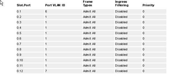
13.在Switch>VLAN>Port config页下面查看端口的PVID,1端口应为6,12端口应为7,其余为1。
14.设置完成。
二、通过CLI命令行设置 NETGEARGSM7312交换机Port-Base Vlan
(GSM7312) >enable
Password:
(GSM7312) #vlan database
//进入VLAN设置
(GSM7312) (Vlan)#vlan 6
//创建Vlan6
(GSM7312) (Vlan)#vlan name 6 vlan6
//设置VLAN6名字
(GSM7312) (Vlan)#vlan 7
(GSM7312) (Vlan)#vlan name 7 vlan7
(GSM7312) (Vlan)#exit
(GSM7312) #configure
//进入全局配置模式
(GSM7312) (Config)#interface 0/1
//进入端口配置模式
(GSM7312) (Interface 0/1)#vlan participation include 6
//设置端口属于VLAN 6
(GSM7312) (Interface 0/1)#no vlan tagging 6
//端口不打Tag标记
(GSM7312) (Interface 0/1)#vlan pvid 6
//设置端口PVID
(GSM7312) (Interface 0/1)#exit
(GSM7312) (Config)#interface 0/11
(GSM7312) (Interface 0/11)#vlan participation include 6
(GSM7312) (Interface 0/11)#vlan participation include 7
(GSM7312) (Interface 0/11)#no vlan tagging 6
(GSM7312) (Interface 0/11)#no vlan tagging 7
(GSM7312) (Interface 0/11)#exit
(GSM7312) (Config)#interface 0/12
(GSM7312) (Interface 0/12)#vlan participation include 7
(GSM7312) (Interface 0/12)#no vlan tagging 7
(GSM7312) (Interface 0/12)#vlan pvid 7
(GSM7312) (Interface 0/12)#exit
(GSM7312) (Config)#exit
(GSM7312) #copy system:running-config nvram:startup-config
//存盘
Are you sure you want to save? (y/n) y
Configuration Saved!
(GSM7312) #show vlan 1
//查看Vlan1状态
VLAN ID: 1
VLAN Name: Default
VLAN Type: Default
slot/portCurrentConfiguredTagging
-------------------------------------
0/1IncludeIncludeUntagged
0/2IncludeIncludeUntagged
0/3IncludeIncludeUntagged
0/4IncludeIncludeUntagged
0/5IncludeIncludeUntagged
0/6IncludeIncludeUntagged
0/7IncludeIncludeUntagged
0/8IncludeIncludeUntagged
0/9IncludeIncludeUntagged
0/10IncludeIncludeUntagged
0/11IncludeIncludeUntagged
0/12IncludeIncludeUntagged
(GSM7312) #show vlan 6
VLAN ID: 6
VLAN Name: vlan6
VLAN Type: Static
slot/portCurrentConfiguredTagging
-------------------------------------
0/1IncludeIncludeUntagged
0/2ExcludeAutodetectUntagged
0/3ExcludeAutodetectUntagged
0/4ExcludeAutodetectUntagged
0/5ExcludeAutodetectUntagged
0/6ExcludeAutodetectUntagged
0/7ExcludeAutodetectUntagged
0/8ExcludeAutodetectUntagged
0/9ExcludeAutodetectUntagged
0/10ExcludeAutodetectUntagged
0/11IncludeIncludeUntagged
0/12ExcludeAutodetectUntagged
(GSM7312) #show vlan 7
VLAN ID: 7
VLAN Name: vlan7
VLAN Type: Static
slot/portCurrentConfiguredTagging
-------------------------------------
0/1ExcludeAutodetectUntagged
0/2ExcludeAutodetectUntagged
0/3ExcludeAutodetectUntagged
0/4ExcludeAutodetectUntagged
0/5ExcludeAutodetectUntagged
0/6ExcludeAutodetectUntagged
0/7ExcludeAutodetectUntagged
0/8ExcludeAutodetectUntagged
0/9ExcludeAutodetectUntagged
0/10ExcludeAutodetectUntagged
0/11IncludeIncludeUntagged
0/12IncludeIncludeUntagged
(GSM7312) #show vlan port all
PortAcceptableIngressDefault
slot/port VLAN ID Frame TypesFilteringGVRPPriority
--------- ------- ------------ ----------- ------- --------
0/16Admit AllDisableDisable0
0/21Admit AllDisableDisable0
0/31Admit AllDisableDisable0
0/41Admit AllDisableDisable0
0/51Admit AllDisableDisable0
0/61Admit AllDisableDisable0
0/71Admit AllDisableDisable0
0/81Admit AllDisableDisable0
0/91Admit AllDisableDisable0
0/101Admit AllDisableDisable0
0/111Admit AllDisableDisable0
0/127Admit AllDisableDisable0
(GSM7312) #
三、.通过Web页面设置 NETGEARGSM7312交换机802.1Q Vlan

设置目标:
在GSM7312上增加建立6个Vlan:Vlan2-7,其中端口1打标记属于VLAN2、VLAN3,端口12打标记属于VLAN4、VLAN5,2-5端口不打标记属于VLAN6,6-9端口不打标记属于VLAN7,10端口不打标记属于VLAN1,11端口打标记属于所有VLAN与上级交换机上连。
端口 |
PVID |
VLAN1 |
VLAN2 |
VLAN3 |
VLAN4 |
VLAN5 |
VLAN6 |
VLAN7 |
1 |
1 |
T |
T |
T |
|
|
|
|
2 |
6 |
|
|
|
|
|
U |
|
3 |
6 |
|
|
|
|
|
U |
|
4 |
6 |
|
|
|
|
|
U |
|
5 |
6 |
|
|
|
|
|
U |
|
6 |
7 |
|
|
|
|
|
|
U |
7 |
7 |
|
|
|
|
|
|
U |
8 |
7 |
|
|
|
|
|
|
U |
9 |
7 |
|
|
|
|
|
|
U |
10 |
7 |
U |
|
|
|
|
|
|
11 |
1 |
T |
T |
T |
T |
T |
T |
T |
12 |
1 |
T |
|
|
T |
T |
|
|
配置步骤
1. 使用9针串口设置线连接GSM7312交换机,进入CLI配置界面,使用(GSM7312)# Clear Config命令恢复出厂设置。
2.然后使用命令(GSM7312)#Reload ; 系统提示是否保存现有配置(选择YES)。然后系统重新启动。
3.配置GSM7312交换机管理IP地址为192.168.0.238/24,配置完毕后保存。
4.连接配置计算机的网线到GSM7312的端口10;
5. 打开IE浏览器,在URL处输入http://192.168.0.238/,进入交换机配置管理界面。
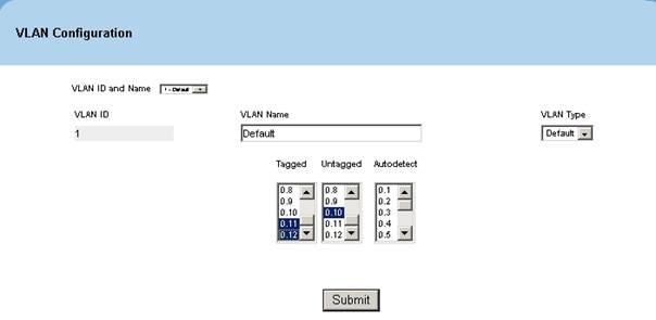
6. 点选菜单Switch>VLAN>config ;在VLAN Configuration界面的Default VLAN处选择进行端口配置,1,11,12标记在Tagged、10标记在Untagged;

7. 在VLAN Configuration界面的VLAN ID and Name处,下拉选择Create选项进行新的VLAN的创建。
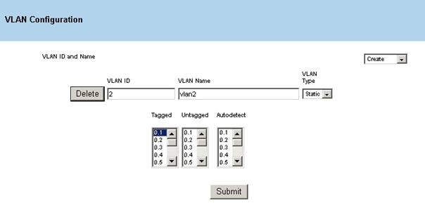
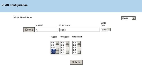
8.在VLAN ID栏里输入2; VLAN Name处输入:VLAN2 ;
VLAN type选:Static(缺省)
然后,按住键盘CTRL的同时,用鼠标点在Tagged栏目下点选端口1、11,然后点“Submit”按纽保存设置。(见下图)
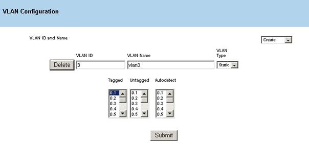
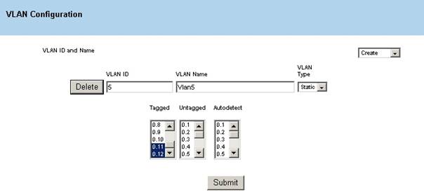
- 重复7-8步骤过程,建立VLAN3,添加端口1,11在Tagged。建立VLAN4,VLAN5添加端口11,12在Tagged。
VLAN3:
VLAN4:

VLAN5:
//查看Vlan1状态
VLAN ID: 1
VLAN Name: Default
VLAN Type: Default
slot/portCurrentConfiguredTagging
-------------------------------------
0/1IncludeIncludeUntagged
0/2IncludeIncludeUntagged
0/3IncludeIncludeUntagged
0/4IncludeIncludeUntagged
0/5IncludeIncludeUntagged
0/6IncludeIncludeUntagged
0/7IncludeIncludeUntagged
0/8IncludeIncludeUntagged
0/9IncludeIncludeUntagged
0/10IncludeIncludeUntagged
0/11IncludeIncludeUntagged
0/12IncludeIncludeUntagged
(GSM7312) #show vlan 6
VLAN ID: 6
VLAN Name: vlan6
VLAN Type: Static
slot/portCurrentConfiguredTagging
-------------------------------------
0/1IncludeIncludeUntagged
0/2ExcludeAutodetectUntagged
0/3ExcludeAutodetectUntagged
0/4ExcludeAutodetectUntagged
0/5ExcludeAutodetectUntagged
0/6ExcludeAutodetectUntagged
0/7ExcludeAutodetectUntagged
0/8ExcludeAutodetectUntagged
0/9ExcludeAutodetectUntagged
0/10ExcludeAutodetectUntagged
0/11IncludeIncludeUntagged
0/12ExcludeAutodetectUntagged
(GSM7312) #show vlan 7
VLAN ID: 7
VLAN Name: vlan7
VLAN Type: Static
slot/portCurrentConfiguredTagging
-------------------------------------
0/1ExcludeAutodetectUntagged
0/2ExcludeAutodetectUntagged
0/3ExcludeAutodetectUntagged
0/4ExcludeAutodetectUntagged
0/5ExcludeAutodetectUntagged
0/6ExcludeAutodetectUntagged
0/7ExcludeAutodetectUntagged
0/8ExcludeAutodetectUntagged
0/9ExcludeAutodetectUntagged
0/10ExcludeAutodetectUntagged
0/11IncludeIncludeUntagged
0/12IncludeIncludeUntagged
(GSM7312) #show vlan port all
PortAcceptableIngressDefault
slot/port VLAN ID Frame TypesFilteringGVRPPriority
--------- ------- ------------ ----------- ------- --------
0/16Admit AllDisableDisable0
0/21Admit AllDisableDisable0
0/31Admit AllDisableDisable0
0/41Admit AllDisableDisable0
0/51Admit AllDisableDisable0
0/61Admit AllDisableDisable0
0/71Admit AllDisableDisable0
0/81Admit AllDisableDisable0
0/91Admit AllDisableDisable0
0/101Admit AllDisableDisable0
0/111Admit AllDisableDisable0
0/127Admit AllDisableDisable0
(GSM7312) #
三、.通过Web页面设置 NETGEARGSM7312交换机802.1Q Vlan
设置目标:
在GSM7312上增加建立6个Vlan:Vlan2-7,其中端口1打标记属于VLAN2、VLAN3,端口12打标记属于VLAN4、VLAN5,2-5端口不打标记属于VLAN6,6-9端口不打标记属于VLAN7,10端口不打标记属于VLAN1,11端口打标记属于所有VLAN与上级交换机上连。
端口 |
PVID |
VLAN1 |
VLAN2 |
VLAN3 |
VLAN4 |
VLAN5 |
VLAN6 |
VLAN7 |
1 |
1 |
T |
T |
T |
|
|
|
|
2 |
6 |
|
|
|
|
|
U |
|
3 |
6 |
|
|
|
|
|
U |
|
4 |
6 |
|
|
|
|
|
U |
|
5 |
6 |
|
|
|
|
|
U |
|
6 |
7 |
|
|
|
|
|
|
U |
7 |
7 |
|
|
|
|
|
|
U |
8 |
7 |
|
|
|
|
|
|
U |
9 |
7 |
|
|
|
|
|
|
U |
10 |
7 |
U |
|
|
|
|
|
|
11 |
1 |
T |
T |
T |
T |
T |
T |
T |
12 |
1 |
T |
|
|
T |
T |
|
|
配置步骤
1. 使用9针串口设置线连接GSM7312交换机,进入CLI配置界面,使用(GSM7312)# Clear Config命令恢复出厂设置。
2.然后使用命令(GSM7312)#Reload ; 系统提示是否保存现有配置(选择YES)。然后系统重新启动。
3.配置GSM7312交换机管理IP地址为192.168.0.238/24,配置完毕后保存。
4.连接配置计算机的网线到GSM7312的端口10;
5. 打开IE浏览器,在URL处输入http://192.168.0.238/,进入交换机配置管理界面。
6. 点选菜单Switch>VLAN>config ;在VLAN Configuration界面的Default VLAN处选择进行端口配置,1,11,12标记在Tagged、10标记在Untagged;
7. 在VLAN Configuration界面的VLAN ID and Name处,下拉选择Create选项进行新的VLAN的创建。
8.在VLAN ID栏里输入2; VLAN Name处输入:VLAN2 ;
VLAN type选:Static(缺省)
然后,按住键盘CTRL的同时,用鼠标点在Tagged栏目下点选端口1、11,然后点“Submit”按纽保存设置。(见下图)

- 重复7-8步骤过程,建立VLAN3,添加端口1,11在Tagged。建立VLAN4,VLAN5添加端口11,12在Tagged。
VLAN3:

VLAN4:
VLAN5:
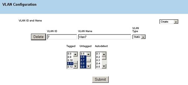
9. 重复7-8步骤过程,建立VLAN6,添加端口2-5端口在Untagged,11在Tagged。建立VLAN7,添加端口6-9端口在Untagged,11在Tagged。
VLAN6:
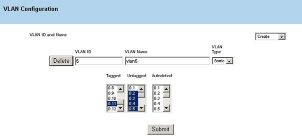
VLAN7:
10.点选菜单Switch>VLAN>Port config ;在Port Vlan ID右边栏里输入:1;点选端口1,11,12;然后按”Submit”更改端口1,10,11,12的PVID;
11.重复第10步,在Port Vlan ID右边栏里输入:6;点选端口2-5;然后按”Submit”更改端口2-5的PVID;在Port Vlan ID右边栏里输入:7;点选端口6-9;然后按”Submit”更改端口6-9的PVID;
2-5:
6-9:
12.选择菜单薄Switch>VLAN>status ,查看VLAN包含端口情况,VLAN1应包含1,10,11,12端口,Vlan2,Vlan3包含1,11端口,Vlan4,Vlan5包含11,12端口,Vlan6包括2-5,11端口,Vlan7包括6-9,11端口。

13.在Switch>VLAN>Port config页下面查看端口的PVID,2-5端口应为6,6-9端口应为7,其余为1。
14.设置完成。
四、通过Web页面设置 NETGEARGSM7312交换机802.1Q Vlan
(GSM7312) >enable
Password:
(GSM7312) #vlan database
(GSM7312) (Vlan)#vlan 2
(GSM7312) (Vlan)#vlan name 2 vlan2
(GSM7312) (Vlan)#vlan 3
(GSM7312) (Vlan)#vlan name 3 vlan3
(GSM7312) (Vlan)#vlan 4
(GSM7312) (Vlan)#vlan name 4 vlan4
(GSM7312) (Vlan)#vlan 5
(GSM7312) (Vlan)#vlan name 5 vlan5
(GSM7312) (Vlan)#vlan 6
(GSM7312) (Vlan)#vlan name 6 vlan6
(GSM7312) (Vlan)#vlan 7
(GSM7312) (Vlan)#vlan name 7 vlan7
(GSM7312) (Vlan)#exit
(GSM7312) #configure
(GSM7312) (Config)#interface 0/1
(GSM7312) (Interface 0/1)#vlan participation include 1
(GSM7312) (Interface 0/1)#vlan participation include 2
(GSM7312) (Interface 0/1)#vlan participation include 3
(GSM7312) (Interface 0/1)#vlan tagging 1
//端口打801.1q标记
(GSM7312) (Interface 0/1)#vlan tagging 2
(GSM7312) (Interface 0/1)#vlan tagging 3
(GSM7312) (Interface 0/1)#vlan pvid 1
(GSM7312) (Interface 0/1)#exit
(GSM7312) (Config)#interface 0/2
(GSM7312) (Interface 0/2)#vlan participation exclude 1
//设置端口不属于default vlan(vlan1)
(GSM7312) (Interface 0/2)#vlan participation include 6
(GSM7312) (Interface 0/2)#no vlan tagging 6
(GSM7312) (Interface 0/2)#vlan pvid 6
(GSM7312) (Interface 0/2)#exit
(GSM7312) (Config)#interface 0/3
(GSM7312) (Interface 0/3)#vlan participation exclude 1
(GSM7312) (Interface 0/3)#vlan participation include 6
(GSM7312) (Interface 0/3)#no vlan tagging 6
(GSM7312) (Interface 0/3)#vlan pvid 6
(GSM7312) (Interface 0/3)#exit
(GSM7312) (Config)#interface 0/4
(GSM7312) (Interface 0/4)#vlan participation exclude 1
(GSM7312) (Interface 0/4)#vlan participation include 6
(GSM7312) (Interface 0/4)#no vlan tagging 6
(GSM7312) (Interface 0/4)#vlan pvid 6
(GSM7312) (Interface 0/4)#exit
(GSM7312) (Config)#interface 0/5
(GSM7312) (Interface 0/5)#vlan participation exclude 1
(GSM7312) (Interface 0/5)#vlan participation include 6
(GSM7312) (Interface 0/5)#no vlan tagging 6
(GSM7312) (Interface 0/5)#vlan pvid 6
(GSM7312) (Interface 0/5)#exit
(GSM7312) (Config)#interface 0/6
(GSM7312) (Interface 0/6)#vlan participation exclude 1
(GSM7312) (Interface 0/6)#vlan participation include 7
(GSM7312) (Interface 0/6)#no vlan tagging 7
(GSM7312) (Interface 0/6)#vlan pvid 7
(GSM7312) (Interface 0/6)#exit
(GSM7312) (Config)#interface 0/7
(GSM7312) (Interface 0/7)#vlan participation exclude 1
(GSM7312) (Interface 0/7)#vlan participation include 7
(GSM7312) (Interface 0/7)#no vlan tagging 7
(GSM7312) (Interface 0/7)#vlan pvid 7
(GSM7312) (Interface 0/7)#exit
(GSM7312) (Config)#interface 0/8
(GSM7312) (Interface 0/8)#vlan participation exclude 1
(GSM7312) (Interface 0/8)#vlan participation include 7
(GSM7312) (Interface 0/8)#no vlan tagging 7
(GSM7312) (Interface 0/8)#vlan pvid 7
(GSM7312) (Interface 0/8)#exit
(GSM7312) (Config)#interface 0/9
(GSM7312) (Interface 0/9)#vlan participation exclude 1
(GSM7312) (Interface 0/9)#vlan participation include 7
(GSM7312) (Interface 0/9)#no vlan tagging 7
(GSM7312) (Interface 0/9)#vlan pvid 7
(GSM7312) (Interface 0/9)#exit
(GSM7312) (Config)#interface 0/10
(GSM7312) (Interface 0/10)#vlan participation include 1
(GSM7312) (Interface 0/10)#no vlan tagging 1
(GSM7312) (Interface 0/10)#vlan pvid 1
(GSM7312) (Interface 0/10)#exit
(GSM7312) (Config)#interface 0/11
(GSM7312) (Interface 0/11)#vlan participation include 1
(GSM7312) (Interface 0/11)#vlan participation include 2
(GSM7312) (Interface 0/11)#vlan participation include 3
(GSM7312) (Interface 0/11)#vlan participation include 4
(GSM7312) (Interface 0/11)#vlan participation include 5
(GSM7312) (Interface 0/11)#vlan participation include 6
(GSM7312) (Interface 0/11)#vlan participation include 7
(GSM7312) (Interface 0/11)#vlan tagging 1
(GSM7312) (Interface 0/11)#vlan tagging 2
(GSM7312) (Interface 0/11)#vlan tagging 3
(GSM7312) (Interface 0/11)#vlan tagging 4
(GSM7312) (Interface 0/11)#vlan tagging 5
(GSM7312) (Interface 0/11)#vlan tagging 6
(GSM7312) (Interface 0/11)#vlan tagging 7
(GSM7312) (Interface 0/11)#vlan pvid 1
(GSM7312) (Interface 0/11)#exit
(GSM7312) (Config)#interface 0/12
(GSM7312) (Interface 0/12)#vlan participation include 1
(GSM7312) (Interface 0/12)#vlan participation include 4
(GSM7312) (Interface 0/12)#vlan participation include 5
(GSM7312) (Interface 0/12)#vlan tagging 1
(GSM7312) (Interface 0/12)#vlan tagging 4
(GSM7312) (Interface 0/12)#vlan tagging 5
(GSM7312) (Interface 0/12)#vlan pvid 1
(GSM7312) (Interface 0/12)#exit
(GSM7312) (Config)#exit
(GSM7312) #copy system:running-config nvram:startup-config
Are you sure you want to save? (y/n) y
Configuration Saved!
(GSM7312) #show vlan 1
VLAN ID: 1
VLAN Name: Default
VLAN Type: Default
slot/portCurrent ConfiguredTagging
-------------------------------------
0/1IncludeIncludeTagged
0/2ExcludeExcludeUntagged
0/3ExcludeExcludeUntagged
0/4ExcludeExcludeUntagged
0/5ExcludeExcludeUntagged
0/6ExcludeExcludeUntagged
0/7ExcludeExcludeUntagged
0/8ExcludeExcludeUntagged
0/9ExcludeExcludeUntagged
0/10IncludeInclude Untagged
0/11IncludeIncludeTagged
0/12IncludeIncludeTagged
(GSM7312) #show vlan 2
VLAN ID: 2
VLAN Name: vlan2
VLAN Type: Static
slot/portCurrentConfiguredTagging
-------------------------------------
0/1IncludeIncludeTagged
0/2ExcludeAutodetectUntagged
0/3ExcludeAutodetectUntagged
0/4ExcludeAutodetectUntagged
0/5ExcludeAutodetectUntagged
0/6ExcludeAutodetectUntagged
0/7ExcludeAutodetectUntagged
序号 no. |
日期 date |
作者 author |
摘要 summary |
1 |
2010-11-1 |
NETGEAR |
文档创建 |